Testing
Hardware
Below is a picture of all supported boards connected to a USB hub. The USB hub is connected to a linux PC (not in the picture) that executes test suites on all boards.
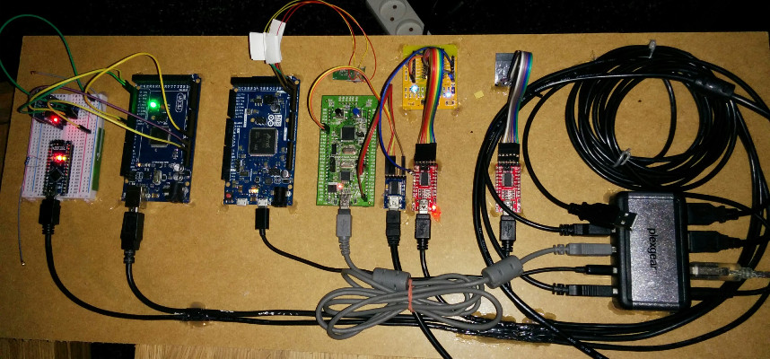
The boards are (from left to right): Arduino Nano, Arduino Mega, Arduino Due, STM32VLDISCOVERY, ESP-12E Development Board and ESP-01
A short description of the setup:
- The DS3231 device (on the breadboard to the left) is connected over i2c to the Arduino Mega.
- CAN0 is connected to CAN1 on the Arduino Due. The CAN driver is tested by sending frames between the two CAN devices.
- The UART of the STM32VLDISCOVERY board is connected to a serial to USB adaptor. DTR on the adaptor is used to reset the board.
- The ESP-12E Development Board also has a serial to USB adaptor connected. RTS is used to set the board in flashing mode (GPIO0) and DTR is used to reset the board (REST).